
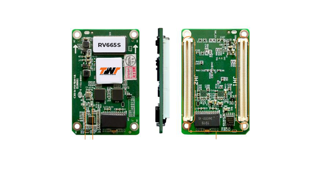
RECEIVING CARD
Model: RV665S
INTRODUCTION
-
The RV665S is a high-end small receiving card developed by TWT. A single RV665S loads up 320×256 pixels (8bit), or 256×256 pixels (10bit/12bit). Supporting the pixel level brightness and chroma calibration, individual Gamma adjustment for RGB, and 3D functions, the RV665S can greatly improve the display effect and user experience.
-
The RV665S uses high-density connectors for communication to limit the effects of dust and vibration, resulting in high stability. It supports up to 32 groups of parallel RGB data or 64 groups of serial data (expandable to 128 groups of serial data). Its reserved pins allow for custom functions of users. Thanks to its EMC Class B compliant hardware design, the RV665S has improved electromagnetic compatibility and is suitable to various on-site setups.
-
The RV665S is a high-end small receiving card developed by TWT. A single RV665S loads up 320×256 pixels (8bit), or 256×256 pixels (10bit/12bit). Supporting the pixel level brightness and chroma calibration, individual Gamma adjustment for RGB, and 3D functions, the RV665S can greatly improve the display effect and user experience.
-
The RV665S uses high-density connectors for communication to limit the effects of dust and vibration, resulting in high stability. It supports up to 32 groups of parallel RGB data or 64 groups of serial data (expandable to 128 groups of serial data). Its reserved pins allow for custom functions of users. Thanks to its EMC Class B compliant hardware design, the RV665S has improved electromagnetic compatibility and is suitable to various on-site setups.
FEATURES
Improvements To Display Effect
- Pixel level brightness and chroma calibration
Working with TWT, the receiving card supports brightness and chroma calibration on each LED, which can effectively remove color discrepancies and greatly improve LED display brightness and chroma consistency, allowing for better image quality.
- Quick adjustment of dark or bright lines
The dark or bright lines caused by splicing of cabinets or modules can be adjusted to improve the visual experience. This function is easy to use and the adjustment takes effect immediately.
-
3D function
Working with the independent controller which supports 3D function, the receiving card supports 3D image output.
-
Individual Gamma adjustment for RGB
Working with TWT (V5.2.0 or later) and the independent controller which supports this function, the receiving card supports individual adjustment of red Gamma, green Gamma and blue Gamma, which can effectively control image non-uniformity under low grayscale and white balance offset, allowing for a more realistic image.
-
Image rotation in 90° increments
The display image can be set to rotate in multiples of 90° (0°/ 90°/180°/270°).
Improvements to Maintainability
- Smart module (supported by dedicated firmware)
-
Working with the smart module, the receiving card supports module ID management, storage of calibration coefficients and module parameters, monitoring of module temperature, voltage and flat cable communication status, LED error detection, and recording of the module run time.
- Automatic module calibration
-
After a new module with flash memory is installed to replace the old one, the calibration coefficients stored in the flash memory can be automatically uploaded to the receiving card when it is powered on.
- Module Flash management
-
For modules with flash memory, the information stored in the memory can be managed. The calibration coefficients and module ID can be stored and read back.
- One click to apply calibration coefficients stored in module Flash
-
For modules with flash memory, if the Ethernet cable is disconnected, users can hold down the self-test button on the cabinet to upload the calibration coefficients in the flash memory of the module to the receiving card.
- Mapping function
-
The cabinets display the receiving card number and Ethernet port information, allowing users to easily obtain the locations and connection topology of receiving cards.
- Setting of a pre-stored image in receiving card
-
The image displayed on the screen during startup, or displayed when the Ethernet cable is disconnected or there is no video signal can be customized.
- Temperature and voltage monitoring
-
The temperature and voltage of the receiving card can be monitored without using peripherals.
- Cabinet LCD
-
The LCD module connected to the cabinet can display the temperature, voltage, single run time and total run time of the receiving card.
- Bit error rate monitoring
-
The Ethernet port communication quality of the receiving card can be monitored and the number of erroneous packets can be recorded to help troubleshoot network communication problems.
- Firmware program readback
-
The firmware program of the receiving card can be read back and saved to the local computer.
- Configuration parameter readback
-
The configuration parameters of the receiving card can be read back and saved to the local computer.
- LVDS transmission (supported by dedicated firmware)
-
Low-voltage differential signaling (LVDS) transmission is used to reduce the number of data cables from the hub board to module, increase the transmission distance, and improve the signal transmission quality and electromagnetic compatibility (EMC).
Improvements to Reliability
- Dual card backup and status monitoring
In an application with requirements for high reliability, two receiving cards can be mounted onto a single hub board for backup. In the case that the main receiving card fails, the backup card will serve to ensure uninterrupted operation of the display. The working status of the main and backup receiving cards can be monitored in TWTV5.2.0 or later.
- Status detection of dual power supplies
When two power supplies are connected, their working status can be detected by the receiving card.
- Loop backup
The receiving cards and the sending card form a loop via the main and backup line connections. If a fault occurs at a location of the lines, the screen can still display the image normally.
- Dual backup of configuration parameters
The receiving card configuration parameters are stored in the application area and factory area of the receiving card at the same time. Users usually use the configuration parameters in the application area. If necessary, users can restore the configuration parameters in the factory area to the application area.
- Dual backup of the application program
Two copies of the application program are stored in the receiving card at the factory to avoid the problem that the receiving card may get stuck due to program update exception.
- Dual backup of calibration coefficients
The calibration coefficients are stored in the application area and factory area of the receiving card at the same time. Users usually use the calibration coefficients in the application area. If necessary, users can restore the calibration coefficients in the factory area to the application area.
Specifications
Maximum Resolution
512×384@60Hz
320×256 pixels (8bit)
256×256 pixels (10bit/12bit)
Rated Power Consumption
2.5 W
Storage Environment Temperature
–25°C to +125°C
Net Weight
93.1 g & 17.3 g
Note: It is the weight of a single receiving card only.
Input Voltage
DC 3.8 V to 5.5 V
DC 3.3 V to 5.5 V
Operating Environment Temperature
–20°C to +70°C
Storage Environment Humidity
0% RH to 95% RH, non-condensing
Packing Box Dimensions
625.0 mm × 180.0 mm × 470.0 mm
Packing Specifications
Each receiving card is packaged in a blister pack. Each packing box contains 100 receiving cards.
Rated Current
0.5V
0.5 A
Operating Environment Humidity
10% RH to 90% RH, non-condensing
Dimensions
145.7 mm × 91.5 mm × 18.4 mm
70.0 mm × 45.0 mm × 7.9 mm
Packing Box Dimensions
378.0 mm × 190.0 mm × 120.0 mm
Packing Specifications
An antistatic bag and anti-collision foam are provided for each receiving card. Each packing box contains 40 receiving cards.
Download